To drive my X-axis I ordered a 20mm trapezium leadscrew with an anti-backlash nut from DamenCNC. Thanks to their quick service this arrived after only a couple of days.
16 and 20 mm trapezium leadscrew
I asked my dad to machine both ends of the 20 mm leadscrew using the lathe of my friend. What should have been an easy exercise became a bit of a challenge. The leadscrew didn't fit through the spindle head so we used a some what non conventional way of using the lathe :)
While my dad was machining the leadscrew I was using the CNC to mill the motor mount. I like to use SketchUp to design parts and CamBam to generate the machine (g-)code.
After spending an afternoon working the lathe and CNC the results are finally there.
To replace the DC motors I ordered three (3Nm 4.2A) stepper motors, drivers and power supply from Longs ebay shop. With their German warehouse the my order arrived within the week.
Later that same day I started connecting every up and I was ready for my first test. For testing I again used my favourite CNC program, LinuxCNC.
With the DC motor under control I started to do my first integration test. The original setup (see my IronMan post) used a unconventional way of turning a rotation into a linear motion, instead of rotating the leadscrew it was rotating the nut. Since I had the all the parts for this setup I thought I would give this a try.
In the photo's below you'll see the DC motor on the back with its shaft poking through the (original metal plate, yes its a bit rough but this is a test setup remember). The motor shaft is connected to the 24mm leadscrew nut via a belt and pulley system (40:30 ratio). I used some nuts and bots to connect the lot to my gantry.
Motor shaft poking through the metal plate
Belt and pulley with 40:30 ratio
Bolted down to the gantry
For the first (see video below) test I just used my Arduino in combination with a small joystick to generate the PWM and DIR signals for the driver. Aligning the motor and leadscrew was more difficult than I thought it would be. For the test in the video I simply used a clamp to hold the leadscrew in place.
After some more testing I still was not happy with the performance, the leadscrew/nut showed a lot (1 or 2 mm) of backlash. Next up was the belt drive test. I build a structure from some left over multiplex to hold the motor and the bearings in place and attached the smallest pulley (20 teeth) I had.
Wauw.... 10000mm/min that's fast!!. Of course going fast is fun and it looks cool but can it also go slow? The next day I started the slow test and at first it looked good, 100mm/min and even slower was possible, but I wanted to know if at these low speeds there was stil enough power to actually mill so I started using my hand to supply some back pressure........ "what's that funny smell?". That funny smell was my motor driver burning up, apparently it wasn't build for this purpose.
It's a shame, after finally getting the motors to work with DE0 Nano and Linux CNC I was really happy, but I think this these motors are not suitable for my final system. Of course some current limiters can protect the driver but I want a better solution for this system..... to be continued
With the basic mechanics in place it is time to get this puppy moving.
For the X and Y axis I'm going to use the two 24V DC motors with quadrature encoders that came with the stuff I bought from the IronMan. These motor have a gear ratio of 70/1 and a optical quadrature encoder with 30 steps/rev; this will give my a total of 2100 encoder step per (axel) revolution.
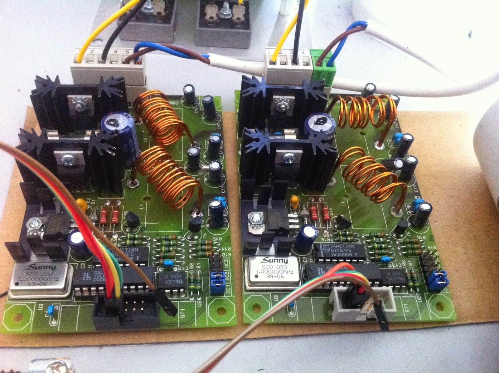
Each motor has its own amplifier board that allows a microprocessor or FPGA (see below) to control the speed via PWM and select the direction by making the DIR pin low/high.
On the top of the board the 24V power comes in via the black (GND) and yellow (24V) wire and goes to the DC motor via the brown blue wire. At the bottom of the board there is a box header with 10 pins where only the first four are applicable.
VCC
VCC
DC Motor PWM
DC Motor DIR
The power for the motors comes from a transformer (round grey thing on the left) and a regulator board (on the right)
For my previous (little) CNC I used a Chinese stepper motor driver and connected this board to my PC via the parallel port. My new motors are not steppers so I started searching for another way to control these motors.
I already used Linux CNC as controller software so this was the place I started by search. In the LinuxCNC manual I found a reference to little board called Pluto-P. This board is based on a Altera FPGA and is able to communicate with a PC via the EPP protocol. Inside the Linux CNC source code folder there is a folder that called Pluto-Servo containing linux driver and FPGA code that allows Linux CNC to control a DC motor with feedback.
I had a DE0 nano (a small dev kit based on a Altera FPGA) laying around for a year or two waiting for a project to come along. The FPGA source code needed some work in order to work with the DE0 nano but this was mostly assigning pins and adding some low pass filters. Source code will be made available when I'm happy with it.
The original Pluto-P board has 5V tolerant IO and can be connected directly to the PC LPT port, the DE0 nano only has 3.3V IO so something needed to be added to translate from 5V to 3.3V. After a quick google I found the a bus transceiver (sn74lvc245a) from TI that can translate 8 signals from 5V to 3.3 and visa versa. Using my amateur EagleCAD skills I created a small PCB that is now connected to LPT port of my PC and the DE0 Nano.
Connecting everything up using my breadboard my test setup looks like this.
On the top there is the power supply connected to the two motor amplifiers. In the bottom right are the two DC motors connected to the amplifier for power. The encoders output of the motors go via the breadboard into the DE0 Nano in the centre and from there via my buffer PCB to my PC. The (modified) pluto-servo code is into the FPGA via the attached USB (JTAG) cable.
For testing purposes I used the (Linux CNC) halrun command and entered the commands listed below. These command configure the pluto_servo driver and attaches a motor encoder to the feedback of a PID controller. The output of the PID controller is attached to the motor PWM pin closing the control loop. The PID settings are still TBD but for this test they work.
The video below shows that by changing the PID command setting the motor reacts by rotating until the setpoint (pid.x.command) is reached.
That's it for now, next is integrating the motors.....