For the X and Y axis I'm going to use the two 24V DC motors with quadrature encoders that came with the stuff I bought from the IronMan. These motor have a gear ratio of 70/1 and a optical quadrature encoder with 30 steps/rev; this will give my a total of 2100 encoder step per (axel) revolution.


Each motor has its own amplifier board that allows a microprocessor or FPGA (see below) to control the speed via PWM and select the direction by making the DIR pin low/high.
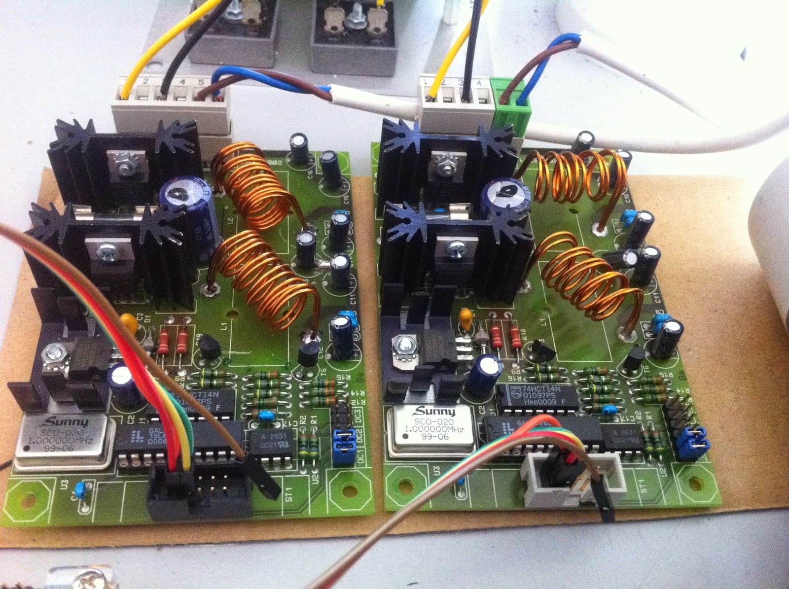
On the top of the board the 24V power comes in via the black (GND) and yellow (24V) wire and goes to the DC motor via the brown blue wire. At the bottom of the board there is a box header with 10 pins where only the first four are applicable.
- VCC
- VCC
- DC Motor PWM
- DC Motor DIR
The power for the motors comes from a transformer (round grey thing on the left) and a regulator board (on the right)

For my previous (little) CNC I used a Chinese stepper motor driver and connected this board to my PC via the parallel port. My new motors are not steppers so I started searching for another way to control these motors.
I already used Linux CNC as controller software so this was the place I started by search. In the LinuxCNC manual I found a reference to little board called Pluto-P. This board is based on a Altera FPGA and is able to communicate with a PC via the EPP protocol. Inside the Linux CNC source code folder there is a folder that called Pluto-Servo containing linux driver and FPGA code that allows Linux CNC to control a DC motor with feedback.
I had a DE0 nano (a small dev kit based on a Altera FPGA) laying around for a year or two waiting for a project to come along. The FPGA source code needed some work in order to work with the DE0 nano but this was mostly assigning pins and adding some low pass filters. Source code will be made available when I'm happy with it.

The original Pluto-P board has 5V tolerant IO and can be connected directly to the PC LPT port, the DE0 nano only has 3.3V IO so something needed to be added to translate from 5V to 3.3V. After a quick google I found the a bus transceiver (sn74lvc245a) from TI that can translate 8 signals from 5V to 3.3 and visa versa. Using my amateur EagleCAD skills I created a small PCB that is now connected to LPT port of my PC and the DE0 Nano.

Connecting everything up using my breadboard my test setup looks like this.

On the top there is the power supply connected to the two motor amplifiers. In the bottom right are the two DC motors connected to the amplifier for power. The encoders output of the motors go via the breadboard into the DE0 Nano in the centre and from there via my buffer PCB to my PC. The (modified) pluto-servo code is into the FPGA via the attached USB (JTAG) cable.
For testing purposes I used the (Linux CNC) halrun command and entered the commands listed below. These command configure the pluto_servo driver and attaches a motor encoder to the feedback of a PID controller. The output of the PID controller is attached to the motor PWM pin closing the control loop. The PID settings are still TBD but for this test they work.
The video below shows that by changing the PID command setting the motor reacts by rotating until the setpoint (pid.x.command) is reached.
That's it for now, next is integrating the motors.....
Linux CNC Hal commands:
loadrt pluto_servo
loadrt threads name1=base-thread period1=100000 name2=servo-thread period2=1000000
loadrt at_pid num_chan=2 debug=1
setp pluto-servo.pwm.0.scale 100
setp pluto-servo.pwm.0.pwmdir 1
setp pluto-servo.pwm.0.enable 1
setp pluto-servo.pwm.1.scale 100
setp pluto-servo.pwm.1.pwmdir 1
setp pluto-servo.pwm.1.enable 1
setp pluto-servo.encoder.0.scale 2100
setp pluto-servo.encoder.1.scale 2100
setp pid.0.Pgain 4000
setp pid.0.Igain 0.3
setp pid.0.Dgain 10
setp pid.0.bias 0
setp pid.0.FF0 0
setp pid.0.FF1 0
setp pid.0.FF2 0
setp pid.0.deadband 0.001
setp pid.0.maxoutput 100
setp pid.0.enable 1
setp pid.1.Pgain 4000
setp pid.1.Igain 0.3
setp pid.1.Dgain 10
setp pid.1.bias 0
setp pid.1.FF0 0
setp pid.1.FF1 0
setp pid.1.FF2 0
setp pid.1.deadband 0.001
setp pid.1.maxoutput 100
setp pid.1.enable 1
net xpos-fb pluto-servo.encoder.0.position => pid.0.feedback
net xvel-cmd pid.0.output => pluto-servo.pwm.0.value
net ypos-fb pluto-servo.encoder.1.position => pid.1.feedback
net yvel-cmd pid.1.output => pluto-servo.pwm.1.value
addf pluto-servo.read servo-thread
addf pluto-servo.write servo-thread
addf pid.0.do-pid-calcs servo-thread
addf pid.1.do-pid-calcs servo-thread
For anyone interested in the DE0Nano code, you can download it here.